Reflection and Refraction Ray Paths
When a wave strikes an interface between two materials with differing physical properties, some of the wave energy will be reflected and the rest will be transmitted through or along the interface. If the incident wave hits the interface at an angle, then the transmitted wave will be refracted, meaning that the angle of the transmitted ray path will be different from the incident angle. This is called “refraction”. The angle can be calculated using Snell’s Law and depends on the seismic velocity of the materials on both side of the interface.
Mode Conversion
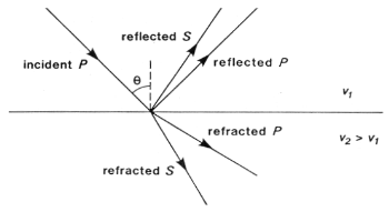
A P-wave incident on an interface at a non-perpendicular angle will produce reflected and transmitted S-waves, as well as P-waves. Analogous conversions occur when there is an incident S wave on a plane boundary. The mode conversions (P \(\rightarrow\) S, or S \(\rightarrow\) P) can complicate interpretation, but S-waves are always slower than P-waves, so first arrivals will always be P-waves unless a special S-wave energy source is used. Interpretation of shear waves is still important in some contexts, especially in geotechnical applications, since they provide important information about the rigidity of the material.

Angles of reflection and refraction
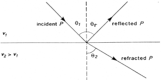
Consider a P-wave which is incident at an angle \(\theta_1\) measured with respect to the normal of the interface, as seen in the figure below where the approaching wave is represented as a ray. The angles of the reflected and refracted rays are as follows:
Law of reflection: The angle of reflection equals the angle of incidence. So \(\theta_r\) = \(\theta_1\) .
Law of refraction: The angle of refraction \(\theta_2\) is determined through Snell’s Law, which is
If the wave travels from a low velocity medium to a high velocity medium the wave gets refracted away from the normal. Conversely, it gets refracted toward the normal if the wave goes from a high velocity to a low velocity medium.

The animation of wavefront propagation shown earlier (and directly below) is again useful here. Although we have described Snell’s law in terms of two rays it captures the bending of a spatially extended wavefront, as the animation clearly shows.
Critical angle
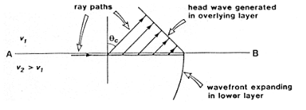
The critical refraction angle, called \(\theta_c\), is a key concept in refraction seismology. This is the angle of incidence for which the corresponding angle of refraction is \(90^{\circ}\). In this case, the refracted ray travels horizontally along the interface. A formula for the critical angle can be derived from Snell’s law as follows:
When the wave in the second medium is critically refracted, it travels parallel to the interface at a speed of \(v_2\). As it travels, it radiates energy into the upper medium with the associated ray path making an angle \(\theta_c\) with the normal. This critically refracted wave is also called a “head wave”. It is somewhat analogous to the bow wave of a moving boat. This is illustrated in the static figure below.

The following video from the IRIS group illustrates the propagation of reflected, sub-critically refracted and critically refracted rays.
We will also once again return to our trusty wavefront animation which shows the head wave in actual wave form, rather than just the head-rays
A final very important point here is to note that energy will only be refracted back toward the surface if the velocity in the lower layer is greater than in the upper layer. Otherwise the ray will be bent toward the vertical downward direction. Examine Snell’s law to convince yourself this is true. This scenario is illustrated below